555 Ic Tester Circuit Diagram 555 Circuit Tester Diagram Sim
555 timer ic tester 555 timer circuit electronics lambert Timer 555 diagram circuit schematic ne555 datasheet pinout block does circuits flop flip works discrete kit eleccircuit integrated functional output
Servo Motor Driver Circuit
Servo motor driver circuit The history of 555 timer ic Draw the pin diagram of ic 555
Free circuit diagrams: ic555 tester circuit
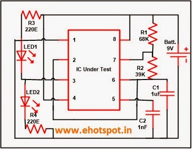
555 tester circuit diagramPin on 555 timer ic tester Timer 555 circuit schematic electronic circuits control ic relay using simple charger schematics board diagrams timing multivibrator battery basic choose555 timer ic testing circuit and its working.
555 timer tester ne555 engineeering555 ic tester circuit ~ electronics hotspot Go look importantbook: ic 555 and cd 4047 measuring electronicsTimer ic 555 tester.

Tester circuit ic timer circuits ic555 schematic diagrams follows complete test
555 timer lm555 cmos invention derivatives circuitstoday555 timer ic testing circuit and its working 555 timer ic555 circuit tester diagram simple ic timer circuits schematic chip test electronic diagrams ic555 pwm control 2011 timers follows complete.
Meters & detectors archivesTransistor circuit tester timer using Dancing light using 555 timerIc circuit tester timer components used.

Electronic – 555 ic – transistor tester – valuable tech notes
Tester ne555 eleccircuit555 ic tester circuit diagram Timer 555 schematicDigital ic tester circuit diagram pdf.
555 ic tester circuit ~ electronics hotspot1 ic led flashing circuit using 555 timer Timer ic block diagram working pin out configuration data sheetSimple 555 ic tester circuit diagram.

555 ic tester circuit diagram
555 timer circuit using light dancing circuits diagram easyeda chip pcb pulse 555timer ne555 projects electronics time astable lm555 modeSimple 555 tester circuit diagram Ic 555 tester circuitDigital ic tester project circuit diagram.
555 ic timer diagram circuit astable pinout pins block description multivibrator ic555 internal structure circuits ground explain figure functional itsIc 555 tester circuit diagram 555 circuit tester diagram list555 timer ic tester.
555 tester circuit
Transistor tester circuit using 555 timerIc circuit tester timer components used How does ne555 timer circuit workIntroduction to the 555 timer.
555 timer ic diagram block ne555 internal wikipedia transistor flop flipIc tester ,op-amp,555 timer tester : 3 steps Tester detectors555 timer diagram block circuit chip does ne555 datasheet inside works work eleccircuit pinout look function.

How does ne555 timer circuit work
.
.


555 Ic Tester Circuit Diagram

Digital Ic Tester Project Circuit Diagram - Circuit Diagram

timer ic 555 tester | Best Engineering Projects

The History of 555 Timer IC - Story of Invention

555 Timer IC Testing Circuit and Its Working

How does NE555 timer circuit work | Datasheet | Pinout | ElecCircuit.com