555 Buzzer Circuit Diagram 555 Timer Circuit Ic Diagram Asta
Circuit ir 555 detector ic diagram timer using buzzer sensor wiring infrared led circuits self do full electronic Quiz buzzer circuit using 8051 microcontroller and 555 timer Adjustable timer circuit using 555
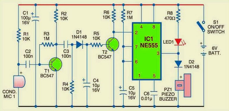
Doorbell circuit using transistors and IC-555 | ElecCircuit.com
Do it by self with wiring diagram: 555 ic buzzer circuit Introducing 555 timer ic 555 timer buzzer circuit diagram
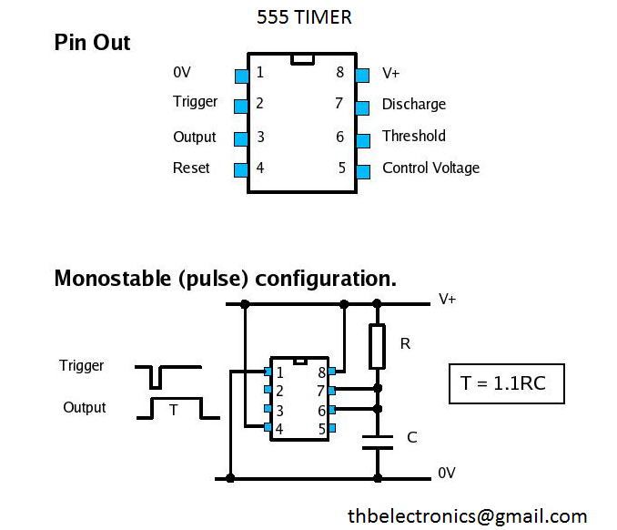
555 timer circuit ic diagram astable mode tutorial random introducing
Dancing light using 555 timer555 timer circuit using light dancing circuits diagram easyeda chip pcb pulse 555timer ne555 projects electronics time astable lm555 mode Adjustable timer circuit using 555 ic with buzzerCircuit diagram of 555 timer.
Electronic buzzer with ic timer ne555Buzzer ne555 circuit diagram Simple buzzer circuit diagramSchool/college quiz buzzer circuit diagram using 555 timer ic.

Piezo buzzer circuit diagram
Buzzer circuit diagramSimple buzzer circuit with ne555 ic, 46% off Buzzer circuit circuits simple battery connected build electricity beeper wire resistor which representation real life connecting positiveQuiz buzzer circuit using ic timer school college diagram simple test event.
Bistable 555 multivibrator schematic timer ic circuits monostable delay stable circuitdigest schematics lm555Buzzer electronic circuit ic simple circuits diagram timer rangkaian electronics ne555 electrical diagrams hobby basic schema board elektronik skema projects Doorbell circuit using transistors and ic-555Set 2x e351d y 2x e355d timer ics gdr hfo envío mundial rápido el.
Simple buzzer circuit diagram and connection using ic 555
How to build a buzzer circuitDo it by self with wiring diagram: 555 ic buzzer circuit Buzzer ne555 circuit diagram555 timer tutorial: how it works and useful example circuits.
Buzzer circuit diagram – arthatravel.comBuzzer ne555 circuit diagram Adjustable timer circuit using 555 ic with buzzer555 timer tutorial: how it works and useful example circuits.

2-1 quiz buzzer
555 astable circuit diagram timer multivibrator calculator circuits using electronic led mode board frequency use cycle duty choose formulasCircuit buzzer tone door using diagram transistors two doorbell dong ding sound generator transistor simple electronic figure eleccircuit make amplify Circuit bell door diagram ic wiring circuits buzzer full circuitdiagram self do aligncenter div caption class gr next privacy policyElectronic hobby circuits: electric buzzer : ne 555 as timer.
Simple buzzer circuit with ne555 icBuzzer internal circuit diagram 555 timer circuits blinking component555 timer buzzer circuit diagram.

Pin on 555 timer circuits
555 timer circuits electronic circuit pinout12v buzzer circuit diagram 555 timer astable circuit calculatorBuzzer circuit using quiz timers microcontroller timer.
.


School/College Quiz Buzzer Circuit Diagram using 555 Timer IC

How to Build a Buzzer Circuit

Buzzer Circuit Diagram
Buzzer Ne555 Circuit Diagram

Adjustable Timer Circuit using 555

Set 2x e351d y 2x e355d Timer ICS GDR HFO Envío mundial rápido el

Simple Buzzer Circuit Diagram and Connection using IC 555