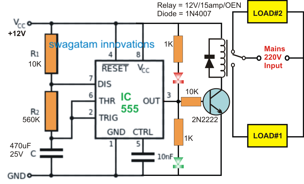
555 Adjustable Timer Circuit Diagram 555 Timer Tutorial: How
Adjustable timer circuit using 555 Timer instructables On off timer circuit diagram
Introduction to the 555 Timer - Circuit Basics
16 hours adjustable timer circuit diagram 555 adjustable timer circuit diagram Timer delay potentiometer wiring
555 timer circuit using light dancing circuits diagram easyeda chip pcb pulse 555timer ne555 projects electronics time astable lm555 mode
555 timer circuit electronics lambertCircuit timer adjustable seekic hours Circuits using 555 timer555 timer tutorial: how it works and useful example circuits.
Timer ic block diagram working pin out configuration data sheetIntroducing 555 timer ic Adjustable timer circuit using 555555 adjustable timer circuit for hours.

Adjustable timer circuit using 555
555 adjustable timer (part-1) : 4 stepsAdjustable timer circuits using ic 555 555 timer ic workingDancing light using 555 timer.
555 timer diagram internal ic astable circuit multivibrator monostable bistable modeCircuit timer circuits using simple make 555 ic diagram switch buzzer adjustable delay minutes button ic555 electronic between connect please Introduction to the 555 timerTimer circuit diagram adjustable electronic minute circuits minutes ic electronics output amperage getting gif using repair projects project schematic.

Adjustable timer circuit using ic 555 – homemade circuit projects
555 timer ic555 timer circuit ic diagram astable mode tutorial random introducing On off delay timer circuit diagram555 timer circuits blinking component.
Electronic circuits diagram: timer circuit 55516 hours adjustable timer circuit diagram 5 hour timer circuit diagram555 timer pin configuration.

How does ne555 timer circuit work
Timer using 555 circuit ic adjustable simple time circuits make desired fixing component altered termed resistor rc timing components above555 timer ic pin diagram features and applications 555 timer ic555 timer ic pin diagram.
Timer ne555 eleccircuit pinout datasheetHow does ne555 timer circuit work .


5 Hour Timer Circuit Diagram

Как работает таймер на гирлянде - 98 фото

Circuits Using 555 Timer

555 Adjustable TIMER (Part-1) : 4 Steps - Instructables

On Off Timer Circuit Diagram

On Off Delay Timer Circuit Diagram - How To Build A Simple Repeating

How does NE555 timer circuit work | Datasheet | Pinout | ElecCircuit.com

Introduction to the 555 Timer - Circuit Basics